

The Reality of PLC Exploitation
In the realm of operational technology (OT) and industrial control systems (ICS), the programmable logic controller (PLC) is the ultimate arbiter of physical reality. It translates digital commands into physical actions—opening valves, spinning turbines, regulating chemical feeds, and maintaining thermal equilibrium. When cyber adversaries successfully compromise these devices, the boundary between virtual exploitation and physical catastrophe dissolves.
On July 22, 2026, the Cybersecurity and Infrastructure Security Agency (CISA), alongside the FBI and the NSA, issued an updated joint advisory detailing persistent, targeted exploitation of PLCs across critical infrastructure sectors. While historical campaigns often focused on specific, niche hardware footprints, this updated advisory highlights a worrying expansion: state-sponsored actors, particularly those affiliated with Iranian cyber groups, are actively targeting mainstream industrial hardware from global giants like Siemens and Schneider Electric, alongside previously targeted systems like Unitronics.
This is not a theoretical threat. It represents an active, systemic campaign targeting unauthenticated industrial protocols, weak access controls, and exposed internet-facing interfaces. As engineering leaders and OT security practitioners, you must look past the sensational headlines and dissect the precise technical mechanisms of these attacks.
In this article, I will analyze the mechanics of PLC logic tampering, evaluate the structural weaknesses of legacy OT protocols, and outline concrete, architecture-level defense strategies. My goal is to move beyond generic security advice and provide you with actionable engineering guidance to harden your physical processes against silent, malicious configuration changes.
Protocol Vulnerabilities: The Core Weakness
To understand why industrial controllers are so vulnerable, I must first analyze the design of legacy industrial protocols. Most protocols in use today—such as Modbus TCP, Siemens S7comm, and EtherNet/IP (Common Industrial Protocol or CIP)—were designed decades ago, long before cybersecurity was a consideration. They prioritize deterministic performance, low latency, and reliability over security. Consequently, they lack basic cryptographic controls.
Modbus TCP
Modbus TCP operates on TCP port 502. It is a simple, request-response protocol that lacks any form of authentication, authorization, or integrity verification. Any device on the network can send a Modbus command to read or write registers. For example, an attacker can send a single packet containing Function Code 6 (Write Single Register) or Function Code 16 (Write Multiple Registers) to alter critical process setpoints or force physical outputs. The protocol does not encrypt payloads, meaning that any actor capable of sniffing network traffic can capture register values and map the entire control system.
Siemens S7comm
S7comm is a proprietary protocol operating on TCP port 102, used for communication between Siemens S7-300/400 PLCs and engineering workstations or HMIs. While more complex than Modbus, legacy S7comm similarly lacks cryptographic authentication. An attacker can establish an S7comm session, send a "Setup Communication" request, and then issue read/write commands to Data Blocks (DBs), inputs (I), outputs (Q), or bit memory (M). Although newer Siemens controllers (S7-1200 and S7-1500) support "S7comm-plus," which introduces cryptographic signing and encryption, many legacy installations still run S7comm in backward-compatibility mode, leaving them exposed.
EtherNet/IP and CIP
EtherNet/IP utilizes the Common Industrial Protocol (CIP) over TCP port 44818 and UDP port 2222. CIP defines standard objects and services for industrial automation. Like its counterparts, standard CIP does not require authentication to execute services such as Set_Attribute_Single or Multiple_Service_Packet. An attacker can abuse these services to modify PLC configuration parameters, force I/O points, or upload new control programs. While CIP Security exists as an extension that implements TLS and DTLS to secure communications, its adoption is limited by legacy hardware constraints and the complexity of managing certificates across thousands of industrial endpoints.
Anatomy of a Logic Tampering Attack
Unlike enterprise IT environments, where attackers often deploy complex malware to escalate privileges and exfiltrate data, OT environments frequently suffer from "living off the land" style attacks that abuse built-in, legitimate engineering functionalities.
The primary vector highlighted in the updated CISA advisory is the exploitation of devices directly exposed to the public internet. This exposure typically occurs due to poor network design, misconfigured cellular gateways, or the legacy practice of exposing engineering workstations via remote desktop protocols (RDP) or virtual phone lines without multi-factor authentication (MFA).
Once an adversary discovers an internet-facing PLC or an adjacent gateway using open-source intelligence tools like Shodan or Censys, the exploitation path is remarkably straightforward. The attack lifecycle generally follows these phases:
- Reconnaissance and Port Scanning: The attacker scans for common industrial ports, such as TCP port 502 (Modbus TCP), TCP port 102 (Siemens S7comm), TCP port 44818 (EtherNet/IP), or UDP port 47808 (BACnet).
- Protocol Handshake and Device Identification: The attacker sends standard read requests to query the device's make, model, firmware version, and memory map. For example, a Modbus
Report Slave IDcommand (Function Code 17) can instantly identify the hardware platform. - Authentication Bypass or Credential Stuffing: If the PLC features a web-based management portal, the attacker attempts to log in using default manufacturer credentials (e.g.,
admin/adminorguest/1234). If the programming interface itself requires no credentials, this step is bypassed entirely. - Logic Upload and Analysis: The attacker uploads the existing control logic (the ladder logic, structured text, or function block diagrams) from the PLC to their local engineering workstation. They analyze the code to identify critical variables, such as safety interlocks, alarm thresholds, or physical setpoints.
- Logic Tampering and Download: The attacker modifies the logic to disable safety limits, override sensor readings, or force physical outputs into unsafe states. They then download the altered program back to the PLC, overwriting the legitimate control logic.
- Denial of Service (DoS) and Bricking: In some cases, the attacker may upload corrupt firmware, change the device's IP address, or set a run-time password that locks out legitimate engineers, effectively bricking the controller and blinding the operators in the control room.
The Mechanics of Logic Tampering and Configuration Exploitation
To understand why these attacks are so devastating, I must look at how PLCs execute code. A PLC operates on a continuous, deterministic cycle: it reads physical inputs, executes its programmed logic, writes physical outputs, and performs system overhead tasks (such as network communications). This is known as the scan cycle.
When an attacker tampers with PLC logic, they alter the execution phase of this cycle. This tampering can manifest in several ways:
- Register Overwriting: The attacker sends direct write commands to specific memory addresses. In Modbus TCP, this involves writing to Holding Registers (Function Code 16) or Coils (Function Code 15). By forcing a coil to a state of
1(ON), an attacker can manually open a valve, regardless of what the safety logic dictates. - Interlock Bypassing: Industrial processes rely on safety interlocks—logical conditions that prevent dangerous operations. For example, a pump should not run if the intake valve is closed. An attacker can modify the ladder logic to bypass these interlocks, forcing the pump to run dry and self-destruct.
- Sensor Spoofing (Man-in-the-Middle): If the PLC relies on analog inputs (e.g., 4-20mA loops converted to integer values), an attacker can insert code that overrides the actual sensor reading with a constant, safe-looking value. While the operators see a normal temperature or pressure on their Human-Machine Interface (HMI), the physical system is actually entering a runaway state.
- Timer and Counter Manipulation: Many processes depend on precise timing (e.g., chemical mixing or cooling cycles). Altering timer presets can ruin product batches or cause physical damage due to premature state transitions.
The fundamental vulnerability here is the lack of integrity verification. Legacy industrial protocols transmit payload data in cleartext without cryptographic signatures. The PLC cannot distinguish between a legitimate command sent by an authorized engineering workstation and a malicious command injected by an attacker on the network.
To detect and prevent these unauthorized modifications, you must implement network-level monitoring that understands these industrial protocols. Below is an example of a Suricata signature designed to detect unauthorized Modbus TCP write commands targeting holding registers on a critical PLC subnet. This rule alerts security teams when any host outside of the designated Engineering Workstation (EWS) IP address attempts to write to the PLC's memory.
alert tcp !$ENGINEERING_WORKSTATION any -> $PLC_SUBNET 502 (
    msg:"OT-IDS: Unauthorized Modbus TCP Write Multiple Registers Attempt";
    flow:established,to_server;
    content:"|00 00|"; depth:2; # Transaction Identifier (wildcarded)
    content:"|00 00|"; distance:2; # Protocol Identifier (always 0 for Modbus)
    byte_jump:2,4,relative,multiplier 1; # Jump over length field
    content:"|10|"; distance:1; # Function Code 16 (0x10) - Write Multiple Registers
    classtype:policy-violation;
    sid:1000001;
    rev:1;
)
Implementing such rules requires a deep understanding of your network's baseline. If your HMI regularly writes to holding registers to update setpoints, you must tune your detection rules to distinguish between normal HMI setpoint adjustments and anomalous engineering commands (such as program downloads or firmware updates).
Architecture-Level Defenses: Network Segmentation and Protocol Hardening
You cannot secure an OT environment by relying solely on endpoint security. Many PLCs lack the computational resources to run local security agents or perform complex cryptographic handshakes. Therefore, the primary line of defense must be a robust, segmented network architecture.
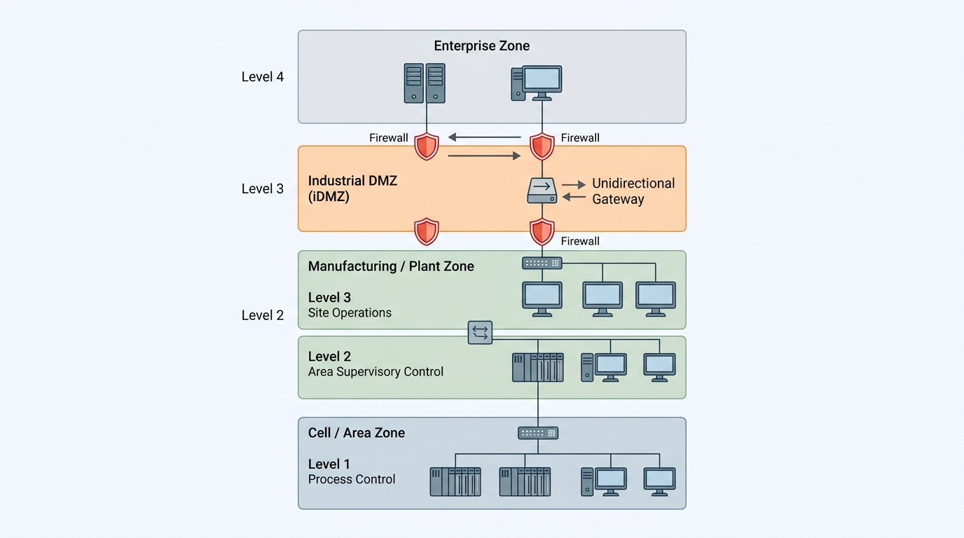
I recommend structuring your network according to the Purdue Model for Control Hierarchy. This model segments the enterprise network (Levels 4 and 5) from the industrial operations zone (Level 3) and the basic control zone (Levels 1 and 2).
| Network Zone | Purdue Level | Core Components | Primary Security Controls |
|---|---|---|---|
| Enterprise Zone | Levels 4 & 5 | Corporate ERP, Email, Active Directory | Multi-factor authentication, EDR, internet gateways, strict patch management. |
| Industrial DMZ (IDMZ) | Boundary | Jump hosts, proxy servers, data historians | No direct traffic allowed between Level 4 and Level 3. Terminate all sessions here. |
| Operations Zone | Level 3 | SCADA servers, HMI servers, engineering workstations | Network-based IDS, centralized logging, patch management for OT operating systems. |
| Basic Control Zone | Level 2 | Local HMIs, supervisory control networks | Strict VLAN segmentation, access control lists (ACLs) limiting HMI-to-PLC traffic. |
| Process Zone | Level 1 | PLCs, RTUs, safety instrumented systems (SIS) | Physical write-protect keys, protocol filtering, disabling unused services (HTTP, FTP). |
To implement these defenses effectively, you must enforce three architectural mandates:
1. Eliminate Direct Internet Exposure
There is zero operational justification for exposing a PLC directly to the public internet. If remote access is required for third-party vendors or off-site engineers, it must terminate at a secure gateway in the Industrial DMZ (IDMZ).
Users must authenticate to the IDMZ using phishing-resistant multi-factor authentication (MFA). From the IDMZ, they must use a secure, monitored jump host to access the engineering workstation in Level 3. The jump host session should be logged, recorded, and restricted using the principle of least privilege.
2. Enforce Unidirectional Data Flows
To send operational data (such as process metrics and alarms) from the OT network to the enterprise network or cloud analytics platforms, do not use bidirectional firewalls. Instead, deploy unidirectional security gateways (data diodes).
These physical devices allow data to flow in only one direction—from the secure OT network to the unsecure enterprise network—using physical fiber-optic transmitters and receivers. This physically prevents any external cyber actor from sending commands back down to the PLCs, completely neutralizing remote execution vectors.
3. Leverage Physical Write-Protect Switches
Most modern PLCs (including those from Siemens, Rockwell, and Schneider Electric) feature a physical key switch or toggle on the front panel of the controller. This switch controls the device's operating mode: RUN, PROGRAM, or REMOTE.
- RUN Mode: The PLC executes the loaded program and ignores any incoming commands to modify the logic or download new code. This is the only mode your PLCs should be in during normal operations.
- PROGRAM Mode: The PLC stops executing the logic and allows engineers to download new code. Physical access is required to turn the key to this position.
- REMOTE Mode: The PLC allows remote engineering workstations to change the run state or download code. While convenient, this mode is highly vulnerable to remote exploitation.
I strongly advise establishing an operational policy that requires all production PLCs to have their physical keys turned to RUN mode. If an engineer needs to modify the program, they must physically walk to the cabinet, turn the key to PROGRAM (or REMOTE), perform the update, and immediately return the key to RUN when finished. This simple physical control completely defeats remote logic tampering attacks.
Operationalizing Detection: Integrity Monitoring and Asset Visibility
Hardening your architecture is a critical first step, but you must also assume that a determined adversary can breach your perimeter. To detect silent logic tampering, you must establish continuous integrity monitoring and comprehensive asset visibility.
Passive Network Monitoring
Active scanning tools (like those used in IT networks) can crash legacy PLCs by overwhelming their limited network stacks with unexpected packets. Therefore, OT security monitoring must rely primarily on passive network monitoring.
By deploying network TAPs (Test Access Points) or configuring SPAN (Switch Port Analyzer) ports on your industrial switches, you can mirror traffic to an OT-specific Intrusion Detection System (IDS). These systems perform Deep Packet Inspection (DPI) on industrial protocols to baseline normal operations.
Your IDS should be configured to alert on the following anomalous events:
- New Device Discovery: Any new MAC or IP address appearing on the control network.
- Unusual Protocol Usage: A host attempting to communicate using an industrial protocol that is not part of its normal profile (e.g., an operator workstation suddenly sending Siemens S7comm commands when it only uses Modbus).
- Configuration Changes: Any command indicating a program upload, download, stop, or cold start targeting a PLC.
- Firmware Updates: Any attempt to flash firmware over the network.
Configuration Baselines and Version Control
To detect unauthorized changes that may have bypassed network detection, you must implement automated configuration baselining. This involves periodically pulling the running program from each PLC and comparing it against a known-good, authorized baseline stored in a secure repository.
Many modern industrial asset management platforms can automate this process. They connect to the PLCs during scheduled maintenance windows, upload the running logic, and perform a byte-by-byte or line-by-line comparison against the master configuration.
If a discrepancy is found—such as a modified setpoint, a deleted interlock, or an altered timer—the system generates an immediate high-priority alert. This approach is highly effective because it detects the result of the tampering, regardless of how the attacker gained access or what techniques they used to hide their network footprint.
Hardening Device Configurations
Finally, you must treat the PLC itself as a hardened host. When deploying new controllers or upgrading existing ones, apply the following device-level security controls:
- Disable Unused Services: Turn off all unnecessary built-in services, such as web servers (HTTP/HTTPS), FTP servers, Telnet, and discovery protocols (like LLDP or UPnP).
- Enable Cryptographic Security Features: If your hardware supports secure protocols (such as OPC UA with encryption, or secure versions of EtherNet/IP and Modbus), enable them. This ensures that communications are encrypted and digitally signed.
- Enforce Strong Local Passwords: If the PLC supports local user accounts or access passwords, change the default credentials immediately to unique, complex passwords. Store these credentials in a secure, offline password vault.
- Enable Logging: Configure the PLC to send syslog data to a centralized SIEM (Security Information and Event Management) system located in the IDMZ. Ensure that logs capture administrative events, such as login attempts, configuration changes, and system restarts.
Conclusion
The updated CISA advisory serves as a stark reminder that the security of our critical infrastructure cannot rely on the assumption of obscurity. Cyber adversaries are actively targeting the foundational components of our physical processes, exploiting structural vulnerabilities that have existed in industrial protocols for decades.
Mitigating the risk of PLC logic tampering requires a shift in mindset. You must move away from reactive, perimeter-only security and embrace a defense-in-depth model that combines physical controls, strict network segmentation, and continuous integrity monitoring.
Your immediate next steps should be clear: audit your OT environment to ensure no PLCs are directly exposed to the internet, enforce the use of physical write-protect keys on your production controllers, and deploy passive monitoring to detect unauthorized configuration changes. By taking these concrete engineering actions, you can build a resilient operational environment capable of withstanding targeted, state-sponsored cyber campaigns.